

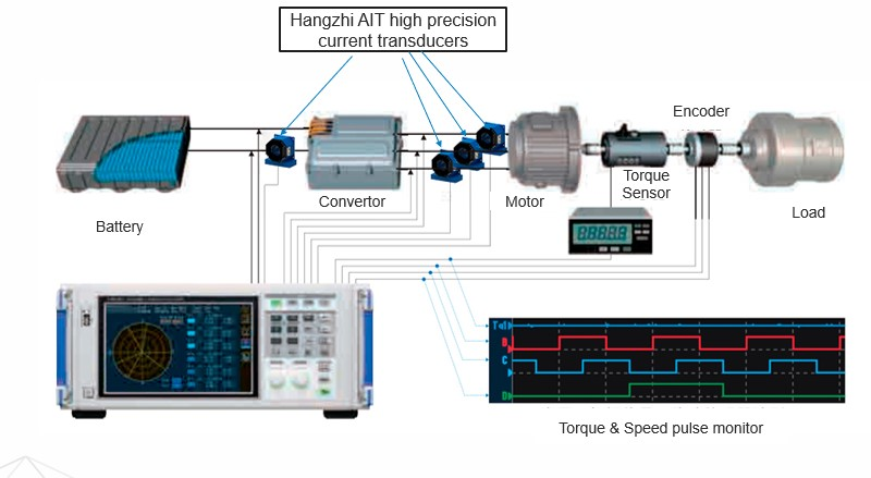
A second technician cannot reproduce a reading from a saved number alone. The output configuration, wiring, load and conversion settings determine what that number represents. In high precision current measurement, a repeatable procedure connects those physical conditions to the reported current.
Preparation establishes a valid signal, conversion restores its primary value, and operating checks establish whether that relationship remains usable. The practical sequence starts at the receiving input, before power is applied or a current value is calculated.
Identify the Output Before Assembling the Connection
An acquisition input configured for voltage cannot be treated as a direct receiver of secondary current. A current-output transducer needs the specified burden arrangement; a voltage-output version instead needs a receiver compatible with its voltage span and loading limit. The receiving instrument’s resolution also limits discrimination between nearby signal levels. Identifying the output variant therefore precedes connector assembly.
Input coverage then separates nominal DC current, AC RMS current and the measuring range. The expected waveform must fit the relevant entries rather than the largest number listed.
For high accuracy current measurement, the chosen device, output type and receiving range form a configuration that can be checked physically. Cable labels and recorded acquisition settings keep that configuration identifiable during subsequent measurements.
Establish the Supply and Initial State
Wiring the Hangzhi AIT200-SG starts with identifying two supply rails and a separate current-output return. Its nominal supply is ±15 V, within ±14.2 V to ±15.8 V. On its D-Sub9 connector, pin 1 is output return, pin 4 ground, pin 5 negative supply, pin 6 current output and pin 9 positive supply. Pins 3 and 8 provide the interlock.
The nominal input ratings are ±200 A DC and 141 A AC RMS, with a ±240 A measuring range. These entries establish the current conditions for this configuration. Its DC accuracy limit is 10 ppm at 25 ±10°C; using the wider measuring range does not remove that temperature condition.
With no primary current, the voltage across the burden resistor is approximately zero. A continuously lit green indicator identifies normal operation after power-up. For high precision current measurement, these observations establish an initial operating state; neither observation proves that the entire acquisition chain has been calibrated. The recorded zero reading remains available for comparison later.
Recover Primary Current from the Secondary Reading
A voltage measured across a burden represents secondary current through the resistance used. The relationship is Ip = Kn × Is = Kn × Ur/Rm, where Ip is primary current, Kn the conversion ratio, Is secondary current, Ur burden voltage and Rm burden resistance. Each symbol identifies a physical part of the conversion.
For the AIT200-SG, the 1000:1 ratio gives ±0.2 A nominal secondary output. As a calculation example, 100 A DC corresponds to 0.1 A secondary and 1 V across 10 Ω. The recorded resistance and voltage units determine how the calculation is implemented. Confusing millivolts with volts changes the reconstructed current by a factor of one thousand, even when the sensor and connected resistance remain unchanged.
The burden is typically 10 Ω, with a 30 Ω maximum subject to the model’s burden curve. High accuracy current measurement requires the actual resistance used in conversion to agree with the connected circuit. A resistor change alters the voltage at unchanged secondary current, so the acquisition scaling must remain tied to that resistance and its permitted operating conditions.
Keep the Output Valid During Operation
An intact secondary circuit is an operating requirement for the AIT200-SG. Its output must remain connected whenever primary current flows or the sensor is powered. Disconnection is permitted only when primary current is absent and the sensor is unpowered. Removing the load while primary current flows or the sensor is powered violates this requirement.
Abnormal output initiates a configuration check rather than an immediate change to the conversion factor. On a Hangzhi AIT sensor, checking supply voltage and supply wiring with a multimeter precedes inspection of both the operating and the power indicators. A corrected supply connection cannot establish whether the original burden value or acquisition setting was appropriate.
After any correction, the recorded input range, output connection and resistance need comparison with the actual arrangement. Repeating the initial zero observation under its original conditions can reveal whether the baseline changed, without identifying every possible error source by itself.
Recheck the Procedure for a Voltage Output
Changing to AIT100-10V changes the receiving task: nominal output is ±10 V, with maximum output-load current of 5 mA. Its nominal input is ±100 A DC or 70 A AC RMS, and its measuring range is ±120 A. The burden values of the current-output example do not define this connection.
For high accuracy current measurement, this model retains its own 50 ppm DC accuracy limit at 25 ±10°C. The shared AIT family name cannot transfer the AIT200-SG’s 10 ppm figure to this voltage-output configuration. The output variant belongs in the measurement record alongside the selected acquisition settings.
A reproducible record retains the sensor model, output variant, supply, receiving range, conversion settings and observed operating state. Current-output and voltage-output configurations from Hangzhi impose different loading requirements on receivers.
Later readings can then be compared with the configuration that produced the earlier result. Repetition becomes technically meaningful when the current value can be reconstructed from the same identified ratio, connected load and documented operating conditions.


